Tuesday, January 11, 2011

New Z axis couplers and hot bed mount

So the PLA Z rod/motor couplers didn't work quite right.  The PLA is a bit brittle and as I tightened the screws, I heard a bunch of cracking.  It seemed to hold for a bit, but then later the couplers just slid off of the Z motor shafts.  You can see the cracking in the couplers in the following pics.


I milled out new couplers from some aluminium stock I had on hand.  I drilled through at 5mm and then drilled half way through at 8mm.  Then I cross drilled some 3mm holes for set screws and tapped them for m4 threads.  You can see the couplers on the machine in the following pics


And I've gotten a method for hot bed mount done.  I'm using plywood and have the heat bed attached to one sheet and have made it so I can detach the heat bed easily if I need to.  The attachment method allows for easy adjustment to level the bed to the nozzle.  You can see it in the following pics.


I still need to find connectors with sufficient ratings to connect the bed to the electronics.  Also need to decide on how to attach to the electronics.  And then I need to attach the endstops so it can auto home and stop the +Z motion before the belts hit the frame.  I hope to have things done and printing any day now.

Monday, January 3, 2011

New year, new machine

So last year I was working on my repstrap, and made good progress.  I built the machine based on the wolfstrap design.  It underwent some changes from my initial design.  I had originally built it with 1/4"-20 threaded rod as leadscrews, but I found it was a bit slow.  I then swapped out the x and y axis for belts.  This worked well, and I was able to get some calibration pieces printed, but I could not quite get the backlash out of the system.  I had my machine in my garage because of its size.  It was based on an Ikea Rast nightstand as the X gantry, so it was rather large.  With the weather turning cold in the winter, I was no longer able to get good extrusion because of the temps, and when it did work, the objects would not stick to the build platform.  I decided to fast track my mendel build so I would have something to work with over the winter.  I bought a set of PLA parts for a Prusa Mendel and completed the build right before the end of the year.  Here are some pics of the machine.

Here's an overview shot

I printed out a replacement Y motor holder out of abs to use instead of the larger design that I purchased.

You can see in the pic below that the placement of the fender washers block one of the 3 motor mount holes. I don't think this will be a problem, but we will see as I start to use the machine.


The belt clamps that came in the kit did not fit the spacing for the X carriage, so I cut some out of wood to use.

For the bed, I used springs from the hardware store.  They are a little long and take some force to mount them but it should work well to help level the bed.

I've got a RAMPS board soldered up that I need to connect up.  The wires from the steppers are short and terminated with JST connectors.  I'm planning on cutting those connectors off and soldering on new wires to connect to the RAMPS board.  I need to buy some cables to do the extension, and then I'll have the machine up and running.

One last issue I ran into was how to mount the extruder.  I have a stepper extruder with a 26:1 geared stepper that is about 4 inches long.  The problem is that the end of the motor hits the belt when I have it mounted front to back.  I will have to work out some method to mount it so that it does not hit the belts.  I may just build the wade's extruder that was included in the PLA kit I bought if I can't get the geared stepper to fit.  The gearhead weighs a good deal too, so the wade's design would be lighter as well so I may go that direction.

Wednesday, November 17, 2010

Finally some pics

Here are a bunch of pics of my machine and the progress I've made over the last few weeks/months.

Here's a shot of my electronics setup at the moment.  You can see the yellow shield board that used to hold the carriers.  You can see the blue screw terminals that used to hold the stepper controllers when I first started.  The green boards on the right were my first stepper carrier board version.  The board in the lower left corner connected with the large rainbow cable is my new 4 axis controller that I am testing.


Here's a pic of my heated build platform.  it is an electric skillet.  It is nice because it has it's own temp regulator.  I set the dial by checking the temp with an IR thermometer.  It holds the temp very stable.

And here's a pic of my brutstruder with the geared stepper.


And here's a pic of all the pololus and the LEDs going all flashy flashy

That's all for now.

a new extruder and another revision of stepper electronics

So I got my geared stepper in and it worked ok my MDF extruder, until the MDF started to split where I had some screws going in through the thickness of the MDF instead of through the face of it.  I went to my local hackerspace and printed out a brutstruder.  The print took about 4.5 hours on the slow Darwin in the space.  The makerbot was being calibrated at the time for a mendel print (a bunch of these were being printed and settings tweaked http://www.thingiverse.com/thing:4730), so I had to use the slower machine in the space.  The extruder works well now and I have to adjust my settings to get it working.

My plan for a heated build platform is to use an electric skillet sitting on my Y stage.  The first tests with the new extruder failed because the filament did not stick to the painters tape I had on the platform.  The heated skillet should help with adhesion.

I have also made up a new 4 axis stepper controller that has further reduced my electronics footprint.  You can see it and read the build instructions at http://www.johnyang.com/p4ac.  I had a batch made up, so if you're interested in one, drop me a note at lj.johnyang*AT*gmail*DOT*com and we can work things out.  I'm still testing things out for the next few days/week to make sure there aren't any problems with the design.

The next thing I have to do is to calibrate my machine and get it printing.  It is very close now.  I'll be trying to print a cathederal for my kids as a holiday present.  After that the next thing I have lined up I want to print is a mendel (most likely the imperial prusa mendel variant) and a replacement shell for the key fob for my car.  it is cracked and I have not had the remote for some months because of it.  I've had to actually use my key to open the car door, the horror!

Anyhow, I hope to be fully printing soon!

Thursday, October 21, 2010

New extruder stepper

So my attempt at a direct drive extruder with a stepper was a failure.  not enough torque to push the filament through the hot end.  There are designs to deal with the usual low torque of nema17 steppers.  There's Adrian's geared extruder, and then there's the popular Wade's extruder.  Rick over at Makergear is working on using a geared stepper in a direct drive extruder.  It's not out yet, but I figured a geared stepper should have enough force to use in my ugly mdf extruder.  Rick's sold out of his motors or they're all allocated for the extruder kits he's presold or something.  I dug around and found a different motor that should provide similar performance here.  It's essentially a nema17 stepper with a 26.8:1 gear reduction.  so it takes 26.8 turns of the stepper to turn the output shaft one turn.  so some quick math here: 200 steps per revolution * 26.8 = 5,360.   I think wade's gear ratio is 3.54:1.  we'll see how this works out.

RepG and the 5D firmware play nice

so I loaded up the Joaz fork of the 5D firmware I have been using on my repstrap and loaded up the latest commits of Erik's RepG changes to get it working with 5D.  I got it working and was able to control axis motion with RepG.  Thinking back, I think the tonokip firmware might have worked last night too if I had pushed the reset button like you have to do on machine connect.  The serial communications kept saying 'serial line non-responsive' or something to that effect.  The problem I found was that when you connect repg to the machine, it expects some text back from the machine.  I had the firmware booted and it was happily waiting there for gcodes.  It took me a few minutes of reloading the firmware and restarting repg and changing and checking serial baud rates before one time it said connected and the bar went green.  I clicked the reset machine button in repg and it could not reconnect.  digging through the source code for repg, I traced down the error message and determined that repg was waiting 10 seconds for some activity on the serial line.  So I shut stuff down, restarted repg, clicked the connect button, then hit the reset button on my mega and it connected right up.  I tried this a few times, and it worked every time.  Finally figured out the problem!  Then I go looking through the wiki wondering why I didn't remember this step and there it is all written out about having to hit the mobo reset button when you connect since repg v3.  Reminder to self: read the fucking manuals.  Next step is to see if the tonokip will work with repg too.

repstrap is almost all done

So it has been a while, and I have finished the Cartesian robot portion, and I made up an MDF extruder, but it does not work well.  The firmware is in and I can control it and 'print' stuff with a pencil and repsnapper.  I finally brought the camera down to the shop to take some pics.  It's an ugly machine, but it is all mine!  Here are a bunch of pics and descriptions.

Here's an overview of the whole printer

Here's a shot of the Y axis stepper and S-belt config used for motion. 

I re-did the X axis to be like the Y axis as well.  I had initially had it as a continous loop with the X/Z carriage clamped to the belt for motion, but I had a bunch of backlash/whiplash with these cheap belts so I changed it up so that there wouldn't be so much spring back when the direction changed.

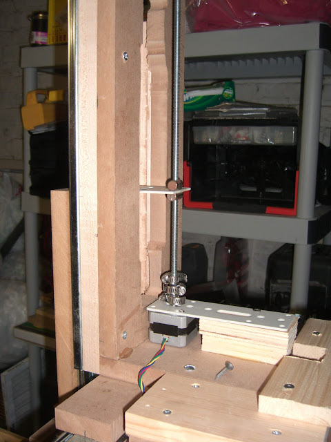
and here's an overview of the back of the machine.

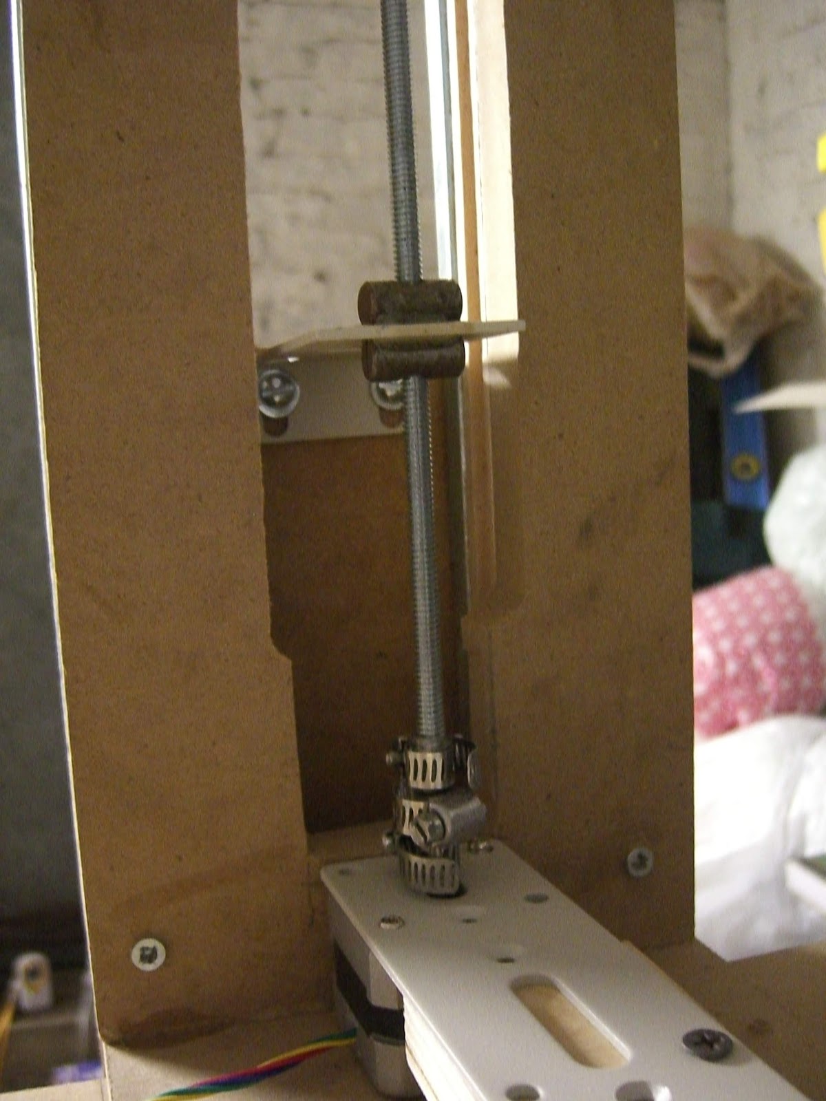
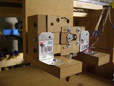
The Z axis uses a threaded rod as you can see above.  The stepper is on a mount and  floating above the X sled.  It looks like it is sitting on it, but there is a small gap there.  The threaded rod is 1/4-20.  The lead nut is made up of two barrel nuts epoxied to two sides of a metal mount (rack mount ear from some old datacenter equipment).  It's not quite an anitbacklash setup since there's no spring pushing the two nuts apart to take up the slack, but there is very little slop in this config for the moment.  The attachment between the stepper and the leadscrew is just some tubing held on with clamps.  I have to find a different way to attach this.  The stepper shaft will skip in the tubing if things bind.  This may be a good thing, but I'd rather have a solid connection here so I'll probably change it out when I get a chance.


I have min and max endstops made up as well.  They are not connected to the machine at the moment, but I will find appropriate locations and put them on so the printer can auto home when it starts a print.  I made up mechanical endstops using a contact switch and soldering on the support electronics directly to the switch.  I didn't have the PCB that is designed to hold this stuff and a nice connector, so I just slapped it on the end of some cat5 cable and crimped an end on it to fit on my stepper control boards I designed.  Here is what one looks like when it is not triggered.

And here is what one looks like if it is triggered

And here's an overview shot of my messy electronics setup.  I have an arduino mega, a home made protoboard shield (I bent pins to fit the odd 0.16 spacing of the arduino, what a pain, but this allowed me to use plain protoboard instead of doing up a design to get fabbed or going with a pre-done protoshield.) and 5 of my stepper control boards.  The protoboard takes the ATX power, and has a slide switch so I can kill power to the system to change out wiring easily.  It also has two heater and two thermistor circuits on there.


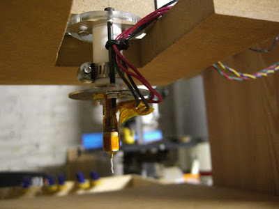
Here's a shot of my MDF extruder.  It looks ulgy, and the stepper isn't strong enough to push the filament into the hot end.  when I try to extrude, it'll push in a bit then the stepper will skip steps and stutter.  It is using a mk5 drive gear, and 5 pieces of mdf, two pieces of masonite, a 608 bearing as the idler and a bunch of screws.  The idler is pushed into the drive gear with a screw that goes through a t-nut in one of the mdf pieces to provide the force.  The hot end is a mk4 setup from MBI.  I bought a MK4 kit when they put them on sale for $60 after the MK5 came out.


And here's a pic of it oozing out some plastic.  I have to attach some insulation on it, but I wanted to keep an eye on it for the first few times to make sure things don't go bad somehow like the nichrome burning things off or shorting out or something.  So close to having this working.  I think I'll have to find/make a geared extruder (a wade's or adrian's) so that the stepper I have can push out the filament.  Or the other option is to get a geared stepper I guess, or a stepper with more torque that can push on through.

So the bulk of my build is now complete.  I'll have to find/adjust my extruder and then I can start building stuff.  And the firmware I am using is the modified-Tonokip used by ultimachine for their RAMPS setup and also the Joaz fork of the 5D firmware.  Both work fine and are configured for my machine right now, so I can switch between them.  Right now, all I can do is the simple XYZ Cartesian motion with a pen taped to the Z axis and both are fine for that.  I'll test out both as I get started printing to see if I have a preference going forward.  So hopefully the next posts will have me with a fully operational printer.